
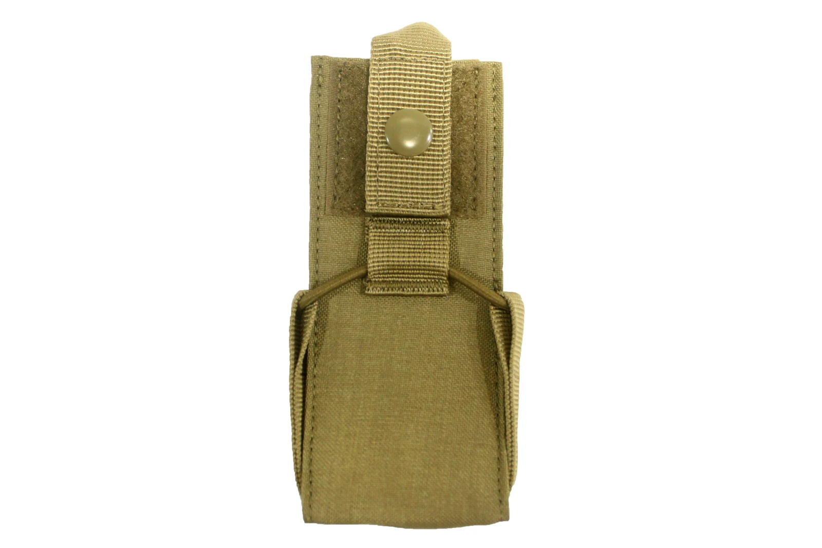
Radio pouch compatibility should cover both insertion and access to the top of the device. A body can fit inside a pouch while a retention strap obstructs a control or a connected plug changes the space required. Develop the complete carried configuration rather than approving the empty pouch outline.
Development priorities: identify the device with its accessories; map areas that must remain clear; inspect the installed position; distinguish adjustment features from confirmed compatibility.
01
Define the complete device configuration
Use the intended radio, battery, belt clip and external connectors during development. If several batteries or clips are available, state which combination forms the reference. Bare-device dimensions do not describe every assembled configuration.
The Zentauron manufacturer selection guidance identifies device dimensions, mounting and access to controls as selection factors. That general principle is relevant here. Its product dimensions and performance claims do not apply to the company sample illustrated in this article.
Keep the equipment reference identifiable even when a physical device cannot be sent. Photographs should show projecting controls and installed accessories, not only the largest body dimensions. A substitute shape needs to reproduce the areas that affect pouch contact.
02
Map clearance around specific components
Mark the antenna base, knobs, display, buttons and connector positions on a device photograph. State which parts need visibility, movement or access, and which simply remain connected. This defines where retention components should pass.
These photographs show an empty pouch. They support observations about the body and upper webbing, but cannot confirm fit for a particular radio. They also provide no evidence about communication performance, cooling or protection of the equipment.
Review the retention arrangement after the radio is inserted. A strap drawn across an empty opening may take a different path over the actual top surface. Record that path before deciding whether a pattern or attachment point needs revision.
03
Inspect clearance after mounting
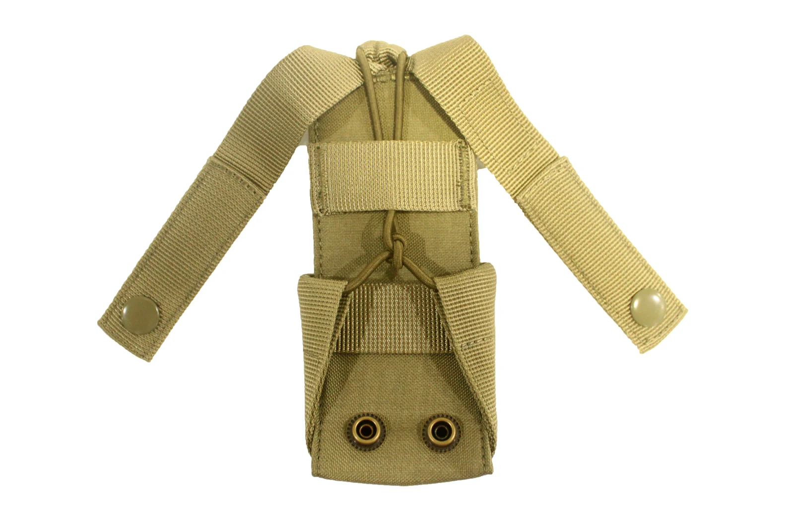
The rear photograph reveals attachment tabs and webbing passages. It does not show a complete installation on a particular belt or pack. Assemble the proposed combination, then observe whether the opening faces the body or adjacent items obstruct controls.
Changing mounting height can change the removal direction and cable route. Keep an installation photograph and the surrounding layout with the sample approval. A generic description of webbing attachment does not establish suitability at every possible position.
When comparing pouch versions, use the same host component. A flexible belt, a loose pack panel and a supported test fixture can present different conditions. Identify that support so the comparison addresses the pouch change rather than an unnoticed installation difference.
04
Check operation with retention secured
With the retention fastened, review the intended display viewing, knob operation, accessory connection and device removal. If an action requires releasing retention, decide whether that sequence meets the intended workflow. Do not leave an unresolved interference for the user to work around.
Follow device-manufacturer guidance for cables. Pouch development can inspect pressure near a plug and crossings with retention parts, but should not invent allowable bend radii or connector loads. Equipment requirements belong in the corresponding documentation.
05
Review side depth and local bulk
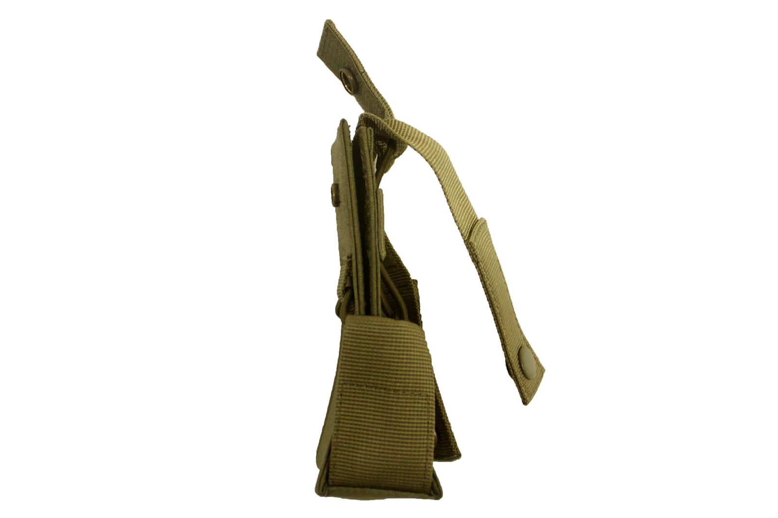
The side view records an opening and layered construction. If insertion catches near the mouth, first locate the contact and identify projecting accessories. Then decide whether to revise depth, side allowance or the edge assembly.
A thinner replacement fabric may also change the opening shape. Recheck the sewn product after substitution rather than comparing weight alone. Colour and visible weave establish neither material composition nor abrasion or connection performance.
Ask the supplier to keep the fabric reference, binding and retention components together in the revision record. This helps avoid approving an exterior appearance while a changed layer alters the space available around the device.
06
Keep a traceable compatibility record
Keep the approved sample identifiable
Register the device and battery version, accessory condition, host component, installation direction and operations reviewed. Mark unconfirmed combinations as pending. The presence of an adjuster does not establish the usable range across every device.
The images are company-library originals. This is a development method, not a device-compatibility certificate or report of completed tests. Explore further construction topics in the JKPD blog.
Related: Hook-and-loop closure development. See the photographed product reference.
Discuss your bag development project
ANSON XIE
General Manager & Founder
Quanzhou Junkai Pengda Special Equipment Co., Ltd.
Email: ansonxie@jkpdtime.com
Phone: +86 177 5095 3355
WhatsApp: +86 177 5095 3355
Factory address: Floors 2–4, Building 1, Phase I, Huixin Intelligent Manufacturing Industrial Park, Hui'an County, Quanzhou, Fujian, China